 a journal of interesting technical ideas . . . a journal of interesting technical ideas . . .
I mentioned a month or so ago that I wanted to set out on a journey to create a set of template networks and then substitute in the various appliances that are supported under GNS3. The idea is to start with Cisco, which I know best, and then explore the differences. I’m still really excited about that but . . . life. So we’re off to a slow start. I’m going to break down some of the topics into smaller pieces so I can keep that project moving forward. First up - how to connect you GNS3 lab environment to a “real” network.
 My home network is built using Meraki gear. That’s not a typical home setup, but I was supporting a lot of Meraki for a while and it was a good way to “eat the dogfood”. I divide the home into subnets so that high risk devices (IoT, kids computers) are isolated. I have an ESXi server that hosts my GNS3 VM, but I haven’t switched over to the web client yet. I’m still using the GNS3 front end running on PopOS!
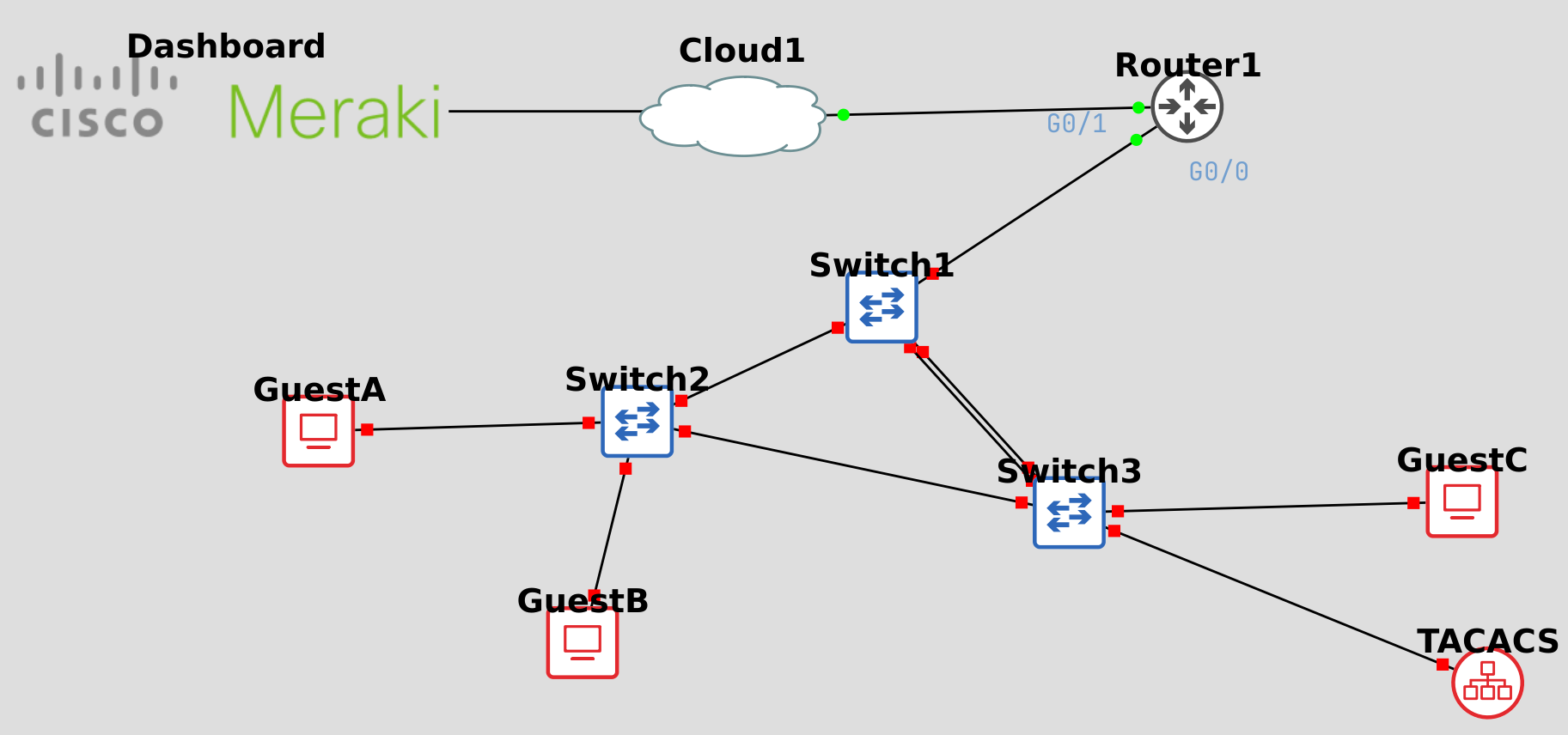
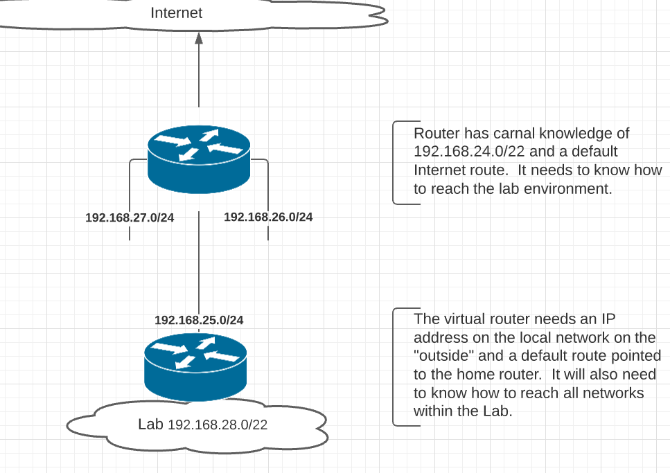
Here’s a diagram of the lab I’m building. In this first step we want to use 192.168.28.0/22 for our GNS3 environment and communicate from it to the local network and the Internet.
My local network is represented by “Cloud1”. I placed this into the lab and attached a connection to the virtual Cisco router. I chose the G0/1 interface when I placed the connection, but this can later be found by hovering over the virtual router in GNS3. You can label connections in GNS3 by clicking the “Show/Hide Inteface Labels” button. In this case I just placed some text.
The Meraki device isn’t really within the GNS3 topology, it’s just a link to the Meraki Dashboard. It’s convenient to have this easily accessible - refer to Adding Hyperlinks to GNS3 Topologies for a walk through on how to do that.
My “real” Meraki router knows how to reach all the local VLANs because it’s directly attached to each of them. It’s going to need to know how to reach the lab environment. This is done under “Security & SD-WAN” > “Addressing and VLANs”. At the bottom of that page is a place for static routes. Identify an IP on the local network that you’ll use for the virtual router and then add a static route.
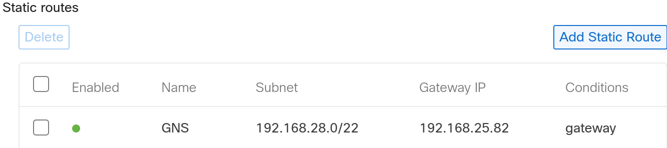
I added a route to 192.168.28.0/22 going to the virtual router. Even though I’m setting up a simple switching lab, giving a block of addresses to the lab means that I won’t have to revisit this process when we start talking about more complicated networks.
The virtual router needs a default route pointing to the home router. It’s also worth noting that I’m not using a DHCP address for the virtual router. You can do this and it will work, but the address will change with each reboot and you’ll need to update the router configuration constantly. Another option would be to use DHCP and a routing protocol. This might be more of an option with another home router, but the Meraki is particularly weak in supporting dynamic routing. Finally, I put an address on the inside of the virtual router.
The following output has been edited for brevity, but shows the added commands and the test ping to Google.
Router# sh run

hostname Router

interface GigabitEthernet0/0
 ip address 192.168.28.1 255.255.255.0
 interface GigabitEthernet0/1
 ip address 192.168.25.82 255.255.255.0
!
ip route 0.0.0.0 0.0.0.0 192.168.25.1

Router#ping __8.8.8.8__
Type escape sequence to abort.
!!!!!
Success rate is 100 percent (5/5), round-trip min/avg/max = 20/25/29 ms
We also want to verify that traffic is flowing from the Internet into our virtual GNS3 lab environment. To do this I’ll source a ping from the G0/0 interface.
Router# ping
Protocol [ip]:
Target IP address: 8.8.8.8
Repeat count [5]:
Datagram size [100]:
Timeout in seconds [2]:
Extended commands [n]: y
Ingress ping [n]:
Source address or interface: 192.168.28.1
Type of service [0]:
Set DF bit in IP header? [no]:
Validate reply data? [no]:
Data pattern [0x0000ABCD]:
Loose, Strict, Record, Timestamp, Verbose[none]:
Sweep range of sizes [n]:
Type escape sequence to abort.
Sending 5, 100-byte ICMP Echos to 8.8.8.8, timeout is 2 seconds:
Packet sent with a source address of 192.168.28.1
!!!!!
Success rate is 100 percent (5/5), round-trip min/avg/max = 20/27/31 ms
Router#
Our lab environment is reachable from the local network and it can reach out to the public Internet as needed at this point. The next step will be to setup the switches!
There’s an associated Github repository for these labs (brentstewart/gns3labs). So far it just has this initial version of the switching lab in it. The topology is there, but it doesn’t have configurations anything other than the router. I’ll continue to refine this lab and add more labs to that repository as we continue this adventure. Please clone the repo and work these with me!